Advanced Topics
Monitoring 802.11n/ac/ax/be Networks
Despite the similarities between the 802.11 a/b/g and 802.11n/ac/ax/be technologies, there are some peculiarities in 802.11n/ac/ax/be networks that influence the way such networks should be efficiently monitored. Without going into the specific technical details of the standard, as they are publicly available from many sources on the Internet, this chapter overviews the best monitoring practices and hardware requirements for 802.11n, 802.11ac, 802.11ax, and 802.11be networks.
Adapter Compatibility
Capturing packets of a particular standard requires the use of the adapter that is based on the same or newer standard. For example, capturing 802.11ac packets requires an 802.11ac or 802.11ax adapter; You cannot capture 802.11ac packets using an 802.11n adapter. The list of compatible adapters can be found on the CommView for WiFi download page on our website. Depending on the configuration of the 802.11n/ac/ax/be WLAN being monitored, additional requirements to the adapter might apply. They are discussed in detail below.
MIMO, Spatial Streams, and Transmit Beam-forming
The use of the MIMO and Transmit Beam-forming technology in 802.11n/ac/ax/be networks is a serious challenge for wireless analyzers. Such networks create a very complex, adaptive signal intensity map with dips and bumps, some as small as a few centimeters in volume. Because a monitoring device is passive, the WLAN being monitored does not attempt to adapt to it. Signals traveling at high rates and transmitted by multiple antennas are also hard to intercept without CRC errors. All of the above means that, generally, you should expect a considerably higher percentage of broken frames when monitoring 802.11n/ac/ax/be networks versus the older 802.11 a/b/g ones. While this is not a problem when you are performing a site survey or measuring signal strength of particular devices, examining individual TCP streams or troubleshooting problems on the per-packet level may become problematic when too many frames are damaged.
To mitigate these 802.11n/ac/ax/be-specific factors, consider applying the following techniques:
- Find the best position for the laptop running CommView for WiFi. Rotating it or moving it just a few inches in a different direction may dramatically increase or decrease the signal quality. In fact, even the position of your body or a raised arm may affect the percentage of CRC errors.
- Try to make sure that that the WLAN devices do not operate at their maximum rates. Successful capturing of packets with rates of 100 Mbps and below is far more likely than successful capturing of packets with higher data rates. Although this sounds counter-intuitive, if your monitoring laptop is located next to the AP, moving the client devices a few meters further from the AP will increase rather than decrease the reception quality. An 802.11ax client device located one or two meters from the AP will almost inevitably transmit packets at the rate of 720 or 866 Mbps, whereas the same device located five meters from the AP will drop the rate down to about 200 Mbps, which is beneficial for our purposes.
It is important to remember that the capabilities of your monitoring adapter in terms of the number of supported spatial streams must exceed or be equal to the capabilities of the WLAN being monitored. In other words, you cannot capture packets being sent from a three-stream AP to a three-stream client using an adapter that supports only one or two spatial streams (but you can capture packets being sent, for example, from a two-stream AP to a two-stream client using a three-stream adapter). It is easy to figure out the number of supported spatial streams by looking at the adapter specifications. For example, for 802.11ac, the maximum supported rate of 433 Mbps means a one-stream adapter, 876 Mbps means a two-stream adapter, and 1,300 Mbps means a three-stream adapter.
Channel Bonding in the 2.4 GHz Band
In modern WLANs, the data rate is optionally increased by bonding two 20 MHz channels (40 MHz operation). The 40 MHz operation uses wider bands, compared to 20 MHz bands in 802.11 a/b/g, to support higher data rates. While a Wi-Fi network analyzer equipped with a 802.11n/ac/ax card does not have a problem with capturing two channels simultaneously, it is important to pay attention to the regulatory domains of the hardware being used. In brief, the frequency of the secondary channel in 40 MHz mode depends on the frequency of the primary channel. For example, selecting channel #1 in your hardware means that the primary 20 MHz channel will operate at the frequency of channel #1, while the secondary 20 MHz channel will operate four channels above the primary one, i.e. at the frequency of channel #5. When operating at higher channel numbers, e.g. 10 or 11, adding four to the channel number would mean that the frequency of the secondary channel would go outside of the regulatory domain constraints: in the US, the top channel in the 2.4 GHz band is 11; in most European countries, the top channel is 13. In such cases, the secondary channel uses the frequency that is below the frequency of the primary channel. For example, selecting channel #10 in your hardware means that the primary 20 MHz channel will operate at the frequency of channel #10, while the secondary 20 MHz channel will operate four channels below the primary one, i.e. at the frequency of channel #6.
The potential problem that a field engineer may encounter when working internationally is that the regulatory domain of his monitoring network adapter may be different from the regulatory domain of the Wi-Fi network being monitored. For example, a Germany-based 802.11n WLAN working on channel #9 would bond channels #9 and #13. A monitoring adapter bought in Canada would expect the secondary channel to be #5. This will prevent the adapter from "seeing" the 40 MHz data streams in the wireless analyzer. To handle this situation, consider using hardware that belongs to the same regulatory domain or use the Sec. channel below in 40 MHz mode box on the Capture pane of the main window. Checking this box will force the adapter to use the secondary channel frequency that is below the primary channel frequency even if the regulatory domain of the network adapter does not require that.
Note that some of the adapters supported by CommView for WiFi, such as Broadcom-based adapters, do not support channel bonding and can capture packets on 20 MHz channels only. Please refer to the Technical Notes for the detailed information. We suggest that you choose one of the adapters marked as Recommended on the download page; such adapters support channel bonding.
Channel Bonding in the 5 and 6 GHz Bands
In the 5 and 6 GHz bands, channel bonding is similar to channel bonding in the 2.4 GHz band, but the number of bonded channels may reach eight in 802.11ac/ax WLANs or sixteen in 802.11be WLANs, which means that channel width may reach 320 MHz. Unlike the 2.4 GHz band, the sets of available bonded channels for the 5/6 GHz band is strictly defined in the standard. For example, for 40 MHz wide channels, channel 52 is always bonded with channel 56; it cannot be bonded with channel 48. For this reason, the Sec. channel below in 40 MHz mode box has no effect when you are capturing channels in the 5 GHz band with a recommended adapter; it automatically selects the correct set of channels. For example, if you select channel 36, the adapter will capture on an 80 MHz wide channel (from 36 to 48). However, in this example, the packets sent using a 20 MHz wide channel would be visible only if they are sent on channel 36. In other words, if you are monitoring a 802.11ac/ax access point that is configured to use channels 36-48 and the AP’s primary channel is 36, you will see both the AP’s beacons and 80 MHz data packets if you are capturing on channel 36, but you will see only 80 MHz data packets (and no beacons) if you are capturing on channel 40, 44, or 48.
BCC and LDPC Coding
On the hardware level, 802.11n/ac/ax/be packets are encoded using either Binary Convolutional Code (BCC) coding or Low Density Parity Check (LDPC) coding. BCC is the default coding method used by the majority of 802.11n devices. LDPC is an optional coding method supported by newer devices. When a client associates to an AP, the HT Capabilities Info element in the association request and association response packets determine the use of one of the two coding methods. For example, if the default BCC mode is being used, the HT Capabilities Info contains the "HT LDPC coding capability: Transmitter does not support receiving LDPC coded packets" field. If the WLAN being monitored uses LDPC coding, your monitoring adapter must support LDPC coding too; otherwise, packets sent at HT rates in one or both directions will be missing or damaged. Capturing LDPC-encoded packets is supported by all the recommended 802.11ac/ax/be adapters.
Understanding CRC and ICV Errors
CRC Errors
Each wireless frame consists of the following basic components:
- A MAC header that includes frame control, duration, address, and sequence control information.
- A variable length frame body that contains information specific to the frame type.
- A frame check sequence (FCS) that contains a 4-byte cyclic redundancy code (CRC).
The last component, FCS, is used to check the integrity of the packet on the receiving end. The receiving end computes the CRC value over the received frame and compares the computed value with the actual four bytes at the end of the packet. If the values mismatch, the packet is considered damaged.
The way CommView for WiFi handles such corrupted frames depends on the user-defined settings. By default, such frames are ignored by the application, with the following exceptions:
- They increment the overall packet and byte counters.
- They increment the CRC Error counter on the Channels tab.
- They are included in the Packet Size chart in the Statistics window.
Damaged frames are not counted in other charts and tables for the obvious reason: No part of a frame with the wrong CRC value is credible. It may have a completely wrong IP address, data payload, etc., although in real life such frames bear a resemblance to the original. For the same reason CRC Errors cannot be attributed to a particular wireless AP or station, as it's impossible to determine the real sender's MAC address.
Nevertheless, the user may want to check the Capture damaged frames box in the options, in which case damaged frames will also be shown in the packet list. By default, such frames are marked with red and have the "CRC" identifier shown in the Errors column of the Packets tab:
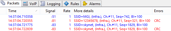
It is important to understand that a frame received with a CRC error by CommView for WiFi may have been received by the destination node without an error. Despite the fact that damaged frames are supposed to be discarded by the destination node without further processing, CommView for WiFi will attempt to decode and even decrypt such frames.
Not all the wireless adapters are capable of passing damaged frames to the application level. Such functionality is guaranteed only for the recommended adapters supported by CommView for WiFi.
ICV Errors
Integrity Check Value (ICV) is a 4-byte checksum used in WEP- and WPA-encrypted frames for verifying the result of decryption. The receiving end computes the ICV value over the data portion of the received frame and compares the computed value with the actual four bytes at the end of the packet's data portion. If the values mismatch, the decryption is considered unsuccessful.
CommView for WiFi is capable of on-the-fly WEP and WPA decryption, provided the correct WEP/WPA key(s) have been entered by the user. The program shows ICV-related information in three different places: On the Nodes and Channels tabs and in the Errors column of the Packets tab. The way ICV errors are shown and counted by the program depends on whether the key has been entered as well as on its correctness. There different cases are possible:
- A key has been entered by the user, and it is correct for the given WLAN.
- A key has been entered by the user, but it is incorrect for the given WLAN.
- No key has been entered.
In the first case, you should see very few ICV errors reported by the program. In the second case, all of the captured data frames will be marked with the ICV Error flag because the computed and the actual ICV values will not match if the wrong key is used for decryption. In the third case, no frames will have ICV errors because no decryption attempts will be made.
As explained above, unlike "hard" CRC errors, ICV errors are "soft" errors that depend on the decryption key. Your WLAN may be perfectly healthy, but if you entered the wrong WEP key in CommView for WiFi, you will observe many ICV errors. Because of its "softness," packets with ICV errors are, by default, shown in the same color as any other packets. This can be changed using the program's Options dialog.
If a frame has a CRC error, detecting an ICV error makes no point. Therefore, CommView for WiFi never sets the ICV error flag for frames with CRC errors.
Understanding WPA Decryption
As it has been mentioned throughout this product's documentation, CommView for WiFi is capable of decrypting WEP- and WPA/WPA2-encrypted network traffic on the fly. To take full advantage of this functionality, you should have a good understanding of the underlying cryptographic principles.
WEP (Wired Equivalent Privacy) is a mechanism used to provide data security in wireless networks. WEP allows the administrator to define a set of keys (or just one key) for the WLAN. These keys are shared among the clients and access points and are used for encrypting data before it is transmitted. If a client does not have the correct WEP key, it cannot decrypt the received packets or send data to other clients, which prevents unauthorized network access and eavesdropping. WEP decryption is rather straightforward as long as you have the correct key. WEP is a static and stateless encryption system, which means that once you have entered the correct key in the WEP/WPA Keys dialog, CommView for WiFi will be immediately able to decrypt packets.
WPA (Wi-Fi Protected Access) came as a replacement for the less secure WEP standard. WPA addresses many of WEP's security and privacy concerns, significantly increasing the level of data protection and access control for WLANs. Unlike WEP, WPA is a dynamic encryption system that uses rekeying, unique per-station keys, and a number of other measures to improve security. WPA features two modes, PSK (Pre-Shared Key) and Enterprise, which differ in a number of ways. CommView for WiFi supports decryption of WPA in PSK mode.
Given the dynamic nature of WPA encryption, knowing the WPA passphrase alone does not allow you to decrypt traffic immediately after entering the correct passphrase. To be able to decrypt WPA-encrypted traffic, CommView for WiFi must be running and capturing packets during the key exchange phase (key exchange is carried out using the EAPOL protocol). It is important that all of the EAPOL key exchange packets be successfully captured. A damaged or missing EAPOL packet will make it impossible for CommView for WiFi to decrypt packets that will be sent to/from the given station, and capturing the next EAPOL conversation between the AP and station may be required. This is an important distinction in the way WEP and WPA traffic is decrypted.
The principles explained above mean that once you have entered the WPA passphrase, closed the WEP/WPA Keys dialog, and started capturing packets, you will need to wait for the next authentication and key exchange event before the packets can be decrypted for the station that has been authenticated. Naturally, it is not uncommon that the program can decrypt packets to/from one client, but not to/from another, as it may have not yet captured EAPOL packets for all of the clients.
Re-authentication can be triggered by using the Node Reassociation tool, by restarting the AP (for all authenticated stations), or by reconnecting to the network (for the given client).
Please note that packet traffic encrypted with WPA3 cannot be decrypted. WPA3 uses the passphrase only for authentication; decryption is impossible.
Understanding Signal Strength
Wireless signal strength is traditionally measured in either percentile or dBm (the power ratio in decibels of the measured power referenced to one milliwatt.) By default, CommView for WiFi displays the signal strength in dBm. The level of 100% is equivalent to the signal level of -35 dBm and higher, e.g. both -25 dBm and -15 dBm will be shown as 100%, because this level of signal is very high. The level of 1% is equivalent to the signal level of -95 dBm. Between -95 dBm and -35 dBm, the percentage scale is linear, i.e. 50% is equivalent to -65 dBm.
If measurements in percentile are preferable, you can switch to percentile by using the Display signal level in dBm option in Settings => Options => Decoding. When the Display signal level in dBm is turned on, the signal strength will be shown in dBm on the Nodes, Channels, and Packets tabs. In the packet decoder tree, the level is always shown in both percentile and dBm.
Capturing A-MPDU and A-MSDU Packets
The 802.11n, 802.11ac, and 802.11ax standards allow sending multiple frames per single access to the medium by combining the frames together into one larger frame. There are two forms of frame aggregation: Aggregated Mac Protocol Data Unit (A-MPDU) and Aggregated Mac Service Data Unit (A-MSDU). CommView for WiFi can capture both types of aggregated packets, as explained below.
Received A-MPDU frames are split into individual packets at the hardware level. A-MPDUs can be up to 64 Kbytes in size. When an A-MPDU is captured, it is passed to the application level as a number of disaggregated packets that look like any other packets. These packets are not marked by CommView for WiFi in any special manner. Support for A-MPDUs is mandatory in modern Wi-Fi standards and it is widely used. A-MPDUs can be captured by any adapter that is supported by CommView for WiFi.
Received A-MSDU frames are split into individual packets at the software level. A-MSDUs can be up to 7,935 bytes in size. When an A-MSDU is captured, it is passed to the application level as a single, aggregated packet—i.e., in the form in which it was originally received. If the aggregated packet is not damaged and if it can be decrypted (if decryption is necessary), CommView for WiFi will disaggregate the A-MSDU and will display the individual packets on the packet list. Such packets will be marked as "Subframe #... of A-MSDU #..." in the "More details" column. Additionally, the subframes will be followed by the original aggregated A-MSDU, which will be marked as "A-MSDU #...." If the aggregated packet is damaged or encrypted, only the original A-MSDU will be displayed. A-MSDUs can be captured by any recommended 802.11ac and 802.11ax adapters.
Note that large frames, such as A-MSDUs, are frequently damaged, especially when being sent at high data rates.
Using CommView for WiFi in a Virtual Machine
You can install and use CommView for WiFi inside a virtualized Windows OS running as a guest operating system on a Mac (or PC, if you prefer a virtual environment for whatever reason). In order to do that, you will need virtualization software, such as VMWare, Parallels Desktop for Mac, or Virtual Box.
Guest Operating System
As a guest Windows version, you can use Windows 10 or 11.
Hardware
To use CommView for WiFi for passive surveys, you need a compatible adapter. When you run our software on a Windows laptop, you can use any of the compatible adapters in different form factors. The list of compatible adapters can be found here. When you run CommView for WiFi inside a virtual Windows machine, you can use USB adapters only. Please refer to the adapter list to find the USB adapter you are going to use. We strongly recommend that you choose an adapter marked "Recommended." They are also always available from us directly when you buy the boxed version.
Virtualization Software Configuration
If your virtualization software supports USB 3.0 emulation (which is the case if you are using VMWare or Parallels Desktop for Mac), be sure to use USB 3.0 emulation rather than USB 2.0 emulation, even if the USB port and the Wi-Fi adapter you are going to use are USB 2.0. USB configuration in VMWare is illustrated below.
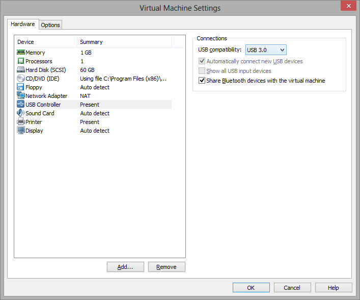
USB 3.0 emulation is preferable because it dramatically increases the communication speed between the Wi-Fi adapter and guest OS. For example, in some adapters, switching the Wi-Fi channel might take 500 or even 1,000 milliseconds if you use USB 2.0 emulation and only 100 milliseconds if you use USB 3.0 emulation. Considering the fact that CommView for WiFi might switch channels every 250 milliseconds, this difference is dramatic. Using USB 2.0 emulation might slow down the application considerably.
For this reason, we recommend that you do not use VirtualBox as virtualization software. At the time of writing, VirtualBox has no USB 3.0 support. If you still want to use VirtualBox, at least use the Enable USB 2.0 (EHCI) Controller option; otherwise, your USB Wi-Fi adapter might not work.
Adapter Installation
Plug in the USB adapter into your computer. Once the adapter is plugged in, you will need to configure your virtualization software to use the detected USB device, i.e. disconnect it from the host OS and connect it to the guest OS. The configuration method depends on the specific virtualization software that you use; please refer to the related documentation. After the virtual machine takes control of the adapter, Windows will notify you that a new USB device has been found and will try to find the driver for the device. Click Help => Driver Installation Guide in CommView for WiFi to find the instructions for installing our special packet capture driver. Once that driver has been installed, you can restart the application and use it.
OFDMA Capturing
CommView for WiFi is capable of capturing OFDMA packets being sent from APs to STAs. This functionality is available only when you use an Intel adapter with Wi-Fi 802.11ax (Wi-Fi 6) support, i.e., you need Intel AX200 or a newer model. If such an adapter is detected, an additional OFDMA panel is shown in the main application window:
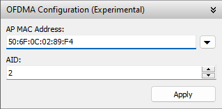
Due to the limitations of the hardware, OFDMA packets won’t be captured until and unless you enter the MAC address of the AP being monitored, as well the Association ID (AID or AID12) of the STA you want to monitor. You can capture only those OFDMA packets that match the provided MAC address and AID parameters; you cannot capture all OFDMA traffic between arbitrary APs and STAs.
The MAC address can be found in virtually any packet, or you can use the arrow button to the right of the MAC address field to select any of the APs that the application currently “sees”.
The AID can be found in CTRL/TRIGGER packets (please remember that CTRL packets are not displayed by CommView by default, you need to press the corresponding button on the toolbar). Once you’ve found a CTRL/TRIGGER packet from the AP to the specific STA you are interested in, you’ll be able to see the AID in the decoder tree:
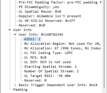
Since it’s not always easy to locate CTRL/TRIGGER packets under heavy traffic load, you may want to use the following formula in Advanced Rules to filter such packets: (ftype=1 and fsubtype=2).
After entering the AP’s MAC address and the STA’s AID, click Apply. This will make the application capture OFDMA traffic (if it’s present) between the specified AP and the client with the specified AID.
Multi-Channel Capturing
CommView for WiFi is capable of capturing data from multiple channels simultaneously if one uses multiple compatible USB adapters.
The following 802.11ac USB adapters can be used for multichannel capturing: ASUS USB-AC68, Belkin F9L1109 v1, D-Link DWA-180 rev A1, D-Link DWA-182 rev C1 or D1, Edimax EW-7822UAC, Edimax EW-7833UAC, EnGenius EUB1200AC, Linksys WUSB6300, Linksys WUSB6400M, NETGEAR A6210, Proxim ORiNOCO 9100, Rosewill RNX-AC1200UB, TP-LINK Archer T4U, TP-LINK Archer T4UH, TP-LINK Archer T9UH v2, TRENDnet TEW-805UB, ZyXEL NWD6605, and ZyXEL AC240. The following 802.11ax USB adapters can be used for multichannel capturing: ASUS USB-AX56, D-Link DWA-X1850, FusionFutures AX1800, NETGEAR A8000, and Alfa AWUS036AXML.
Note that different types of adapters cannot be mixed; all of the adapters should be of the same model. When multiple adapters are connected, the following interface elements are changed:
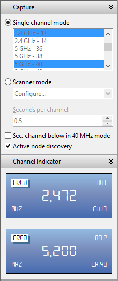
- The channel selection control on the Capture pane allows you to select multiple channels. You can select multiple channels by holding the Ctrl key. The number of channels that you select cannot exceed the number of plugged in USB adapters.
- The Channel Indicator pane displays multiple indicators, the number of which is equal to the number of plugged in USB adapters.
|
This is illustrated on the screenshot. When using multiple adapters, please consider the following: 1. Power consumption. A single adapter might need up to 450 mA of power. A single USB 2.0 port can provide up to 500 mA. A single USB 3.0 port can provide up to 900 mA. A typical modern laptop has two USB 3.0 ports, so you should either use one adapter per port, or you can use a USB hub, but if you plug in three adapters into a USB 3.0 hub, you will exceed the 900 mA limit, which might cause undesirable effects, e.g. the adapters might stop capturing packets silently. 2. Channel switching time. When CommView for WiFi is working in scanner mode, switching channels takes some time, between 20 and 80 milliseconds per adapter. Consider a scan of 12 channels with the scanner interval of 250 ms per channel and the channel switch time of, say, 60 ms. The total time would be (250 + 60) * 12 = 3.72 seconds if you use a single adapter. If you use three adapters, the total time would be (250 + 60 *3) * 4 = 1.72 seconds. That is x2.16 times better, not x3 times better. Thus, adding adapters adds channel switching overhead. If you use 12 adapters, which is possible in theory, it will take 250 + 60 * 12 = 0.97 seconds to scan 12 channels, so you're not gaining much. That said, we don't recommend using more than two or three adapters. |
 |
|
Spectrum Analysis
Spectrum analysis involves the use of special RF equipment designed to listen to and analyze the frequency bands utilized by Wi-Fi devices. Because these bands are unlicensed, they are often shared with non-Wi-Fi sources of RF signals, such as wireless video cameras, microwave ovens, or cordless phones, which cause interference. The purpose of spectrum analysis is to detect and identify such sources of interference, eliminate them, and/or identify the WLAN channels with minimal interference.
Hardware Requirements
CommView for WiFi can perform spectrum analysis simultaneously with packet capturing by interfacing with WiPry or Wi-Spy, USB-based spectrum analyzers. WiPry can be purchased TamoSoft or from Oscium.
|
CommView for WiFi supports the following Wi-Spy models:
|
CommView for WiFi supports the following WiPry models:
|
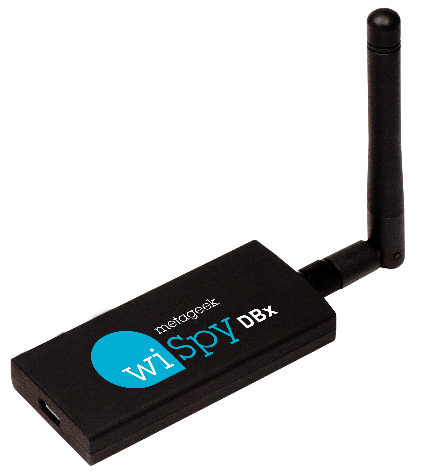
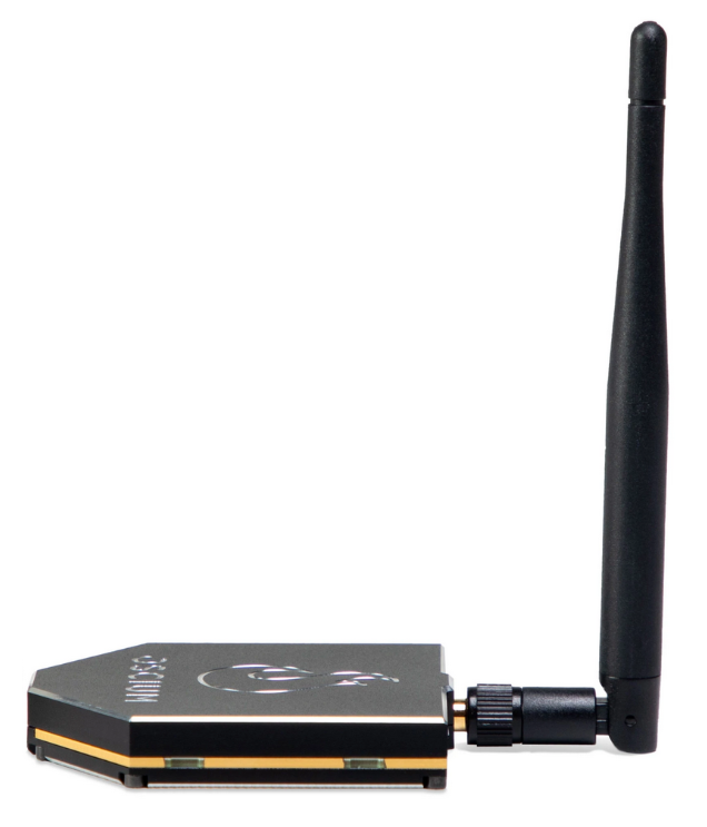
When a multi-band model is used, it continuously sweeps multiple bands, one after the other. Using two Wi-Spy DBx units simultaneously might improve data quality, as CommView for WiFi would dedicate each of the units to one band only. Note that you cannot use two WiPry devices of the same type simultaneously. You can, however, combine WiPry Clarity and WiPry 2500x, and you can mix Wi-Spy and WiPry devices.
Spectrum Data Graphs
When a USB spectrum analyzer is plugged in, a live spectrum picture is displayed on the Channels and Spectrum pane of the main CommView for WiFi window, as shown below.
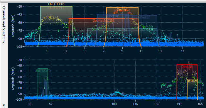
The spectrum pane is similar to the one you can see in Chanalyzer, a spectrum analysis application by MetaGeek that comes with Wi-Spy. By default, the Channels and Spectrum pane displays one or two planar spectrum graphs for single- and dual-band Wi-Spy models, respectively.
The appearance of the graphs can be controlled via the context menu. Select 2.4 GHz, 5 GHz, 6 GHz or Dual to have the spectrum pane display one of the single frequency bands or two of three available bands simultaneously (5 GHz, 6 GHz and Dual are available only if you have a dual-band or tri-band analyzer). Select Current Level to display a line that shows the current signal amplitude; select Max Level to display a line that shows the maximum signal amplitude. The X-axis item allows you to select the measurement units of the horizontal axis; you can choose between Frequency in MHz and Channel numbers. By enabling the Waterfall view, you can have the application graph amplitude over time. Select 1/3, 1/2, or 2/3 of the window size to adjust the area of the window occupied by the waterfall graph. The spectrum pane can be detached from the main application window and displayed as a separate floating window. Use the Detach Window and Attach Window to perform the respective operations. You can also hide the Channels and Spectrum pane by checking or unchecking the View => Channels and Spectrum item in the main application menu.
Note that in order to view spectrum data in CommView for WiFi, you must close Chanalyzer if it is running; Wi-Spy cannot be accessed and controlled by multiple applications simultaneously.
Capturing High Volume Traffic
When capturing data from a large and busy network segment, you should keep in mind that processing thousands of packets per second might considerably increase the CPU usage and make the application less responsive. The best way to optimize the program's performance is to use rules to filter out the packets you do not need to monitor. For example, sending a 50 MB file between two machines on your WLAN can generate approximately 40,000 NetBIOS packets with the data transfer rate of 5 MB per second, which can be a heavy load for the application. However, normally you do not to need to view every NetBIOS packet being sent, so you can configure CommView for WiFi to capture IP packets only. CommView for WiFi has a flexible system of filters, and you can fine-tune the application to display only the packets that you really need. In addition, if you are interested in the statistics information only (those green histograms, pie charts, and hosts tables), you can use the Suspend packet output menu command, which allows you to have statistical data without real-time packet display.
The factors that improve the program's performance:
- A fast CPU (Intel Core i7 is recommended)
- RAM size (8 GB and higher recommended)
- Using rules to filter out unnecessary traffic
Running CommView for WiFi in Invisible Mode
There are two ways to run CommView for WiFi as a hidden process:
- Launch CommView for WiFi with the "hidden" switch, i.e.:
CV.EXE hidden
- If CommView for WiFi is already running, you can hide/unhide it by using the "hot key." To hide the application, press ALT+SHIFT+h. To unhide the application, press ALT+SHIFT+u.
Remember that you cannot completely hide any Windows application. When running in invisible mode, one can still see the CommView for WiFi process in Task Manager.
Command Line Parameters
You can use command line parameters to perform the following operations when the program is being launched:
- Load and activate a rule set from a file. Use the "/ruleset" switch followed by the file name and full path, e.g.:
CV.EXE /ruleset "C:\Program Files\CommViewWiFi\Rules\POP3Rules.rls"
If a file name or its path contains spaces, it must be enclosed in quotation marks (" ").
- Load and activate a WEP/WPA key set from a file. Use the "/keyset" switch followed by the file name and full path, e.g.:
CV.EXE /keyset "C:\Program Files\CommViewWiFi\WLAN3Keys.wep"
If a file name or its path contains spaces, it must be enclosed in quotation marks (" ").
- Use the specified folder for storing log files. Use the /logdir switch followed by the full path to the folder, e.g.
CV.EXE /logdir "C:\Program Files\CommView\Logs"
- Launch the application without the prompt to install the driver. This is useful when you use CommView for WiFi for loading logs collected from other computers or for connecting to Remote Agents. Use the /noprompt switch, e.g.
CV.EXE /noprompt
- Connect to one or several remote agents. Use the "/ra" switch followed by the IP address or hostname of the Remote Agent you'd like to connect to, followed by the password in quotation marks, followed by the channel number that should be monitored (the channel index is 1-based, i.e. if you need to monitor in scanner mode, use "1"; if you need to monitor the first channel, use "2"), e.g:
CV.exe /ra 192.168.0.5 "MyPassword" 2
To connect to multiple Remote Agents from the same CommView for WiFi instance, use a batch file that should look like this:
PING 1.1.1.1 -n 1 -w 5000 >NUL
START "CV" "C:\Program Files\CommViewWiFi\CV.exe" /ra 192.168.0.1 "pwd1" 5
PING 1.1.1.1 -n 1 -w 1000 >NUL
START "CV" "C:\Program Files\CommViewWiFi\CV.exe" /ra 192.168.0.2 "pwd2" 5
PING 1.1.1.1 -n 1 -w 1000 >NUL
START "CV" "C:\Program Files\CommViewWiFi\CV.exe" /ra 192.168.0.3 "pwd3" 5
PING 1.1.1.1 -n 1 -w 1000 >NUL
This script launches CommView for WiFi, waits for 5 seconds to make sure that the application is loaded (we use the PING command to pause because there is no direct way of telling a .BAT file to pause), then we pass to the application the IP addresses, passwords, and adapter numbers of three Remote Agents (with one-second pauses).
You can use all of these parameters, except the last one, at the same time.
Exchanging Data with Your Application
CommView for WiFi provides a simple TCP/IP interface that allows you to process packets captured by CommView for WiFi using your own application in real time. Starting with version 5.0 you may also use this interface for sending packets (similar to the Packet Generator function in CommView for WiFi).
How It Works
CommView for WiFi should be launched with a special command-line argument, "MIRROR", that tells the program to mirror captured packets to an IP address and TCP port of your choice.
Examples:
When CommView for WiFi is launched with a switch like this, it tries to establish a TCP session by connecting to the specified IP address and port number. It means that you should already have your application running and listening on the specified port. If CommView for WiFi fails to establish a connection, it will keep on trying to connect every 15 seconds. The same happens if the connection is broken: CommView for WiFi will try to re-establish it every 15 seconds. If the connection is successfully established, CommView for WiFi sends the packets it captures to the specified IP address as they arrive, in real time.
Data Format
The data is transmitted in NCFX format. Please refer to the CommView Log Files Format chapter for the format description.
Sending Packets
Packets may not only be received by your application but also sent as if you were using Packet Generator. Data can be sent to CommView for WiFi using the same TCP connection over which you are receiving the data. The data format is simple: You should send the packet length (a two-byte unsigned integer in the standard little-endian byte order) followed by the data rate index (a two-byte unsigned integer in the standard little-endian byte order) followed by the packet itself. Packet length should not include the four bytes that precede the packet body. Data rate index is zero-based; it should contain the index of the rate as shown in the Packet Generator. Consider the following example:
String to be sent in hex: D4 00 00 00 80 1F 02 66 C2 8E. The length of this string is 10 bytes.
Rate to be used: 5.5 Mbps. This is the third item in the "802.11 data rate" drop-down list in the Packet Generator.
Resulting buffer to be sent: 0A 00 02 00 D4 00 00 00 80 1F 02 66 C2 8E.
If the adapter is not opened or it does not support packet injection, the packet is silently discarded.
Sample Projects
Two simple demo applications that listen for inbound connections, extract packets from the stream, and display raw data are available.
- https://www.tamos.com/products/commwifi/samp_mirr_c7.zip. This is a Visual Studio project with C++ source code.
- https://www.tamos.com/products/commwifi/samp_mirr_d7.zip. This is a Delphi project with Pascal source code. If you want to compile the project, you will need the popular ICS components suite by Francois Piette, available at https://www.overbyte.be.
Bandwidth
When mirroring data to a remote computer, make sure that the link between CommView for WiFi and the computer to which the data is being mirrored is fast enough to transfer all the data being captured. If CommView for WiFi captures 500 Kbytes/sec, and your link can handle only 50 Kbytes/sec, you'd inevitably have "traffic jams," which might result in various problems (e.g., Winsock may just stop sending data under some Windows versions).
Custom Decoding
CommView for WiFi allows you to use two types of your own custom decoders.
Simple Decoder
If you implement this type of decoder, the output of your decoder will be displayed in the additional column in the Packets tab. Your decoder must be a 32-bit DLL file named "Custom.dll" that exports the only procedure named "Decode." The prototype of this procedure is shown below in C and Pascal:
void __stdcall Decode(unsigned char *PacketData, int PacketLen, char *Buffer, int BufferLen);
} procedure Decode (PacketData: PChar; PacketLen: integer; Buffer: PChar; BufferLen: integer); stdcall;
The DLL must be located in the CommView for WiFi application folder. When you launch CommView for WiFi, it looks for "Custom.dll" in the application folder and loads it into memory. If the "Decode" entry point is found, CommView for WiFi adds a new column named "Custom" to the packet list.
When a new packet is captured and is about to be displayed, CommView for WiFi calls the "Decode" procedure and passes the packet contents to the DLL. The "Decode" procedure must process the packet data and copy the result to the supplied buffer. The first argument is the pointer to the packet data, the second argument is the data length, the third argument is the pointer to the buffer where the results of your decoding must be copied to, and the forth argument is the buffer size (currently always 1024 bytes). The buffer is allocated and freed by CommView for WiFi, so do not attempt to reallocate or free it. The result that you copied to the buffer will be displayed as a string in the "Custom" column.
Your procedure must be fast enough to handle thousands of packets per second; otherwise, it may slow down the application. Do not forget to use the STDCALL calling convention. Two demo DLLs are available. They demonstrate a very simple operation: The output of the "Decode" function is the hex code of the packet's last byte. Your own decoder can be as complex as you wish.
- https://www.tamos.com/products/commview/cust_decoder_c.zip. This is a Visual Studio project with C++ source code.
- https://www.tamos.com/products/commview/cust_decoder_d.zip. This is a Delphi project with Pascal source code.
Complex Decoder
If you implement this type of decoder, the output of your decoder will be displayed as additional items in the packet decoder tree. For information on the implementation of this decoder, please download the following file:
https://www.tamos.com/products/commview/complex_decoder_c7.zip
This type of decoder can be written in Microsoft Visual C++ only, as it is built using C++ classes.
Technical Support
Technical support for custom decoders is provided on the "best effort" basis. We may not be able to answer your programming-related questions.
CommView Log Files Format
CommView and CommView for WiFi use the data format described below for writing captured packets to .NCF or .NCFX files. This is an open data format that you can use for processing log files generated by CommView in your applications, as well as for exchanging data with your application directly (this method is described in this help file).
NCFX Format
This new format was introduced in CommView for WiFi 7.3. Older CommView for WiFi versions and current CommView (non-Wi-Fi) versions use the old NCF format described in the corresponding section below.
Packets are recorded consecutively. Two or more headers, the structure of which is given below, prepend each packet body. All header fields with the length exceeding one byte use little-endian order and are unsigned.
General Header – Mandatory. Length = 20 bytes.
| Field name | Length (bytes) | Description |
| Data length | 4 | The length of the packet, including the length of this and the following headers and including the length of the packet contents (body). |
| Year | 2 | Packet date (year) |
| Month | 1 | Packet date (month) |
| Day | 1 | Packet date (day) |
| Hours | 1 | Packet time (hours) |
| Minutes | 1 | Packet time (minutes) |
| Seconds | 1 | Packet time (seconds) |
| Microseconds | 4 | Packet time (microseconds) |
| Medium type | 1 | The type of the packet medium. 0x01 for Wi-Fi packets, 0x00 for Ethernet packets. |
| Decryption flag | 1 | 0x01 if the packet has already been decrypted by CommView for WiFi and is being saved in decrypted form. 0x00 otherwise. |
| Direction | 1 | For Ethernet packets, packet direction: 0x00 for pass-through, 0x01 for inbound, 0x02 for outbound. For Wi-Fi packets, always 0x00. |
| Reserved1 | 1 | Currently unused |
| Reserved2 | 1 | Currently unused |
RF Header – Mandatory. Length = 20 bytes.
| Field name | Length (bytes) | Description |
| RF Header length | 2 | The length of this header, including the length of all additional extensions (headers), if any. |
| Packet status and modulation | 2 | A bitmask where one or several of the following bits are set:
|
| Frequency band | 2 | 0x40 for 5 GHz, 0x80 for 2.4 GHz, 0x100 for 6 Ghz |
| Channel | 2 | Wi-Fi channel |
| Noise in dBm | 1 | Noise level in dBm, as an unsigned value. E.g., -90 dBm is stored as 90. |
| Signal in dBm | 1 | Signal level in dBm, as an unsigned value. E.g., -30 dBm is stored as 30. |
| Signal in percent | 1 | Signal level as percentage |
| Reserved | 1 | Currently unused |
| PHY Rate | 4 | PHY data transmission rate in Mbps multiplied by 10 |
| Extensions' presence | 4 | A bitmask indicating the presence of additional extensions (headers) following this RF header. For example, if the bits 3, 2, and 0 are set, then this RF header is followed by an extension of type 0, then the extension of type 2, and then the extension of type 3. |
Currently Supported Extensions
MCS Header Type 0 – Optional. Size = 4 bytes.
Note that the MCS Header Type 0 is never added if you capture packets using a pre-802.11ac adapter. MCS information is added only if using 802.11ac or newer adapters for capturing.
| Field name | Length (bytes) | Description |
| MCS Index | 1 | MCS index |
| Number of streams | 1 | Number of MIMO spatial streams less 1; i.e. the 0x00 value means one stream. |
| Channel width | 1 | Channel width If bit 4 of the Packet status and modulation field equals 0 (OFDM modulation): 0x00 – 20 MHz, 0x01 – 40 MHz, 0x02 – 80 MHz, 0x03 – 160 MHz, 0x05 – 320 MHz If bit 4 of the Packet status and modulation field equals 1 (OFDMA modulation): 0x00 - 26-tone RU, 0x01 – 52-tone RU, 0x02 – 106-tone RU, 0x03 – 242-tone RU, 0x04 – 484-tone RU, 0x05 – 996-tone RU, 0x06 – 1992-tone RU (996x2-tone RU) |
| GI | 1 | Guard Interval: 0x00 - 0.8μs, 0x01 - 0.4μs, 0x02 - 1.6μs, 0x03 - 3.2μs |
The packet body follows the headers. The packet body does not contain the 4-byte FCS at the end.
Example #1: A 350-byte long beacon packet sent at the legacy PHY rate of 6 Mbps would be stored as:
[20 bytes of the General Header, in which the Data length field is set to 390] + [20 bytes of the RF header, in which the RF Header length field is set to 20 and in which the Extensions' presence field is set to 0x00000000] + [350 bytes of the packet body]
Example #2: A 1002-byte long data packet sent at the VHT PHY rate of 72.2 Mbps would be stored as:
[20 bytes of the General Header, in which the Data length field is set to 1046] + [20 bytes of the RF header, in which the RF Header length field is set to 24 and in which the Extensions' presence field is set to 0x00000001] + [4 bytes of the MCS Header] + [1002 bytes of the packet body]
NCF Format
This format is used in CommView (any version) and CommView for WiFi version 7.2 and older. Newer CommView for WiFi versions (7.3 and newer) use the NCFX format described in the corresponding section above.
Packets are recorded consecutively. A 24-byte header, the structure of which is given below, prepends each packet body. All header fields with the length exceeding 1 byte use little-endian byte order.
| Field name | Length (bytes) | Description | |||||||||||||||
| Data Length | 2 | The length of the packet body that follows the header | |||||||||||||||
| Source Data Length | 2 | The original length of the packet body that follows the header (without compression). If no compression is being used, the value of this field is equal to the value of the previous field. | |||||||||||||||
| Version | 1 | Packet format version (0 for the current implementation) | |||||||||||||||
| Year | 2 | Packet date (year) | |||||||||||||||
| Month | 1 | Packet date (month) | |||||||||||||||
| Day | 1 | Packet date (day) | |||||||||||||||
| Hours | 1 | Packet time (hours) | |||||||||||||||
| Minutes | 1 | Packet time (minutes) | |||||||||||||||
| Seconds | 1 | Packet time (seconds) | |||||||||||||||
| Microseconds | 4 | Packet time (microseconds) | |||||||||||||||
| Flags | 1 | Bit flags:
|
|||||||||||||||
| Signal Level | 1 | Signal level in percent (applicable to Wi-Fi packets only) | |||||||||||||||
| Rate | 1 | Data transmission rate in Mbps multiplied by 2 (applicable to Wi-Fi packets only) | |||||||||||||||
| Band | 1 | Transmission band. 0x01 for 802.11a, 0x02 for 802.11b, 0x04 for 802.11g, 0x08 for 802.11a-turbo, 0x10 for 802.11 SuperG, 0x20 for 4.9 GHz Public Safety, 0x40 for 5 GHz 802.11n/ac, 0x80 for 2.4 GHz 802.11n/ac. (applicable to Wi-Fi packets only) | |||||||||||||||
| Channel | 1 | Channel number (applicable to Wi-Fi packets only) | |||||||||||||||
| Direction | 1 | For non-WiFi packets, packet direction. 0x00 for pass-through, 0x01 for inbound, 0x02 for outbound. For Wi-Fi packets, the high order byte for the packet rate, if the one-byte Rate field cannot accommodate the value (i.e. the value is higher than 255). | |||||||||||||||
| Signal Level (dBm) | 1 | Signal level in dBm (applicable to Wi-Fi packets only) | |||||||||||||||
| Noise Level (dBm) | 1 | Noise level in dBm (applicable to Wi-Fi packets only) | |||||||||||||||
| Data | Variable | Packet body (unmodified, as transmitted over the media). If the compression flag is set, the data is compressed using the publicly available Zlib 1.1.4 library. The length of this field is recorded in Data Length. |
The total header length is 24 bytes.
If packets are stored in compressed form, the Data Length field contains the length of data after compression, whilst the Source Length field contains the original data length. If a packet is uncompressed, both fields contain the same value.